|
|
|
|
Technical Page Technical Developments in Telephone EngineeringContents
The Parr Barrier
To
print these documents by Roger Parr Click Here
1.
Push-Button Telephone Although push-button
touch-tone telephones made their debut to the general public in 1963, the rotary
dial telephone still was common for many years. In the 1970s the majority of
telephone subscribers still had rotary phones, which in the Bell System of that
era were leased from telephone companies instead of being owned outright. Adoption of the
push-button phone was steady, but it took a long time for them to appear in some
areas. At first it was primarily businesses that adopted push-button phones.
During the mid seventies, in the United Kingdom, Post Office Telecommunications,
THQ (Telephone Headquarters), as it was then called, were investigating the
replacement of the rotary dial with a push button telephone using different
tones for each of the numbers 1 -0 on the existing rotary dial. A major problem
with the dial telephone was premature dialling by the customer, which resulted
in mis- directed or invalid calls. The correct procedure
was on lifting the handset from the telephone cradle, the customer would wait
until a dial tone was sent from the local telephone exchange, to indicate that
the exchange equipment was ready to receive the dialled impulses transmitted by
the customer. The customer then turned the dial clockwise with their finger
placed in the appropriate hole of the dial, representing the number 1 to 0,
until a finger stop was reached on the outside of the dial, preventing further
movement. When the customer removed their finger, the dial would return to its
original position, awaiting the next number, until all numbers had been
forwarded for completion of the call. Often, customers would
pick up the telephone and immediately commence dialling before the exchange
equipment was ready, so that when dial tone was eventually forwarded by the
local telephone exchange, a number of customer dialled digits would have been
lost or clipped, and the call would either be part completed with the exchange
waiting for further pulses from the customers dial in order to route the call
onwards (but none would be forthcoming) or prematurely route the call from the
fewer pulses received to an unknown or invalid route. In both cases, the call
would have to be abandoned. Within Post Office
Telecommunications, THQ, Holborn, London, the design of the touch-tone
telephone, which finally replaced the rotary telephone, was credited to Roger TS
Parr, who introduced new electronic technology employing, among other
sophisticated devices, FIFO chips (First in, First out). This overcame all
problems which might be encountered by customers trying to beat the telephone
exchange dial tone by prematurely transmitting the different tones for each of
the numbers 1 to 0 on the telephone keypad. A prototype of the new
design was taken to Hurstpierpoint telephone exchange in Sussex, where it
underwent stringent trials, the outcome of which was successful. The design was
then handed to Plessey Telecommunications (PTL) who, in turn, then designed the
interface equipment, which was to be inserted in the telephone exchange to
receive the tone pulses for onward routing of the call. It was during the
testing phase with the new interface.that a major problem was encountered. As part of routine
maintenance and testing of telephone exchange equipment by the telephone
engineers, it was customary for the engineers to use a piece of equipment called
a test lamp. This device, the body of which comprised a built-in lamp and a test
probe, was plugged into a convenient power socket located near the piece of
equipment to be tested and by means of a switch located on the test lamp, the
engineer was able to determine different conditions on the equipment under test,
e.g. a voltage, earth or disconnection present. One of these tests was
to extend negative 50 volts from the probe of the test lamp to establish if an
earth condition existed, which would complete or close an electrical circuit and
light the test lamp. When this test lamp condition was used between the line
connecting the new touch-tone telephone design and the interface within the
exchange, due to the interface comprising diodes and transistors, the extension
of negative 50 volts from the test lamp, blew these sensitive devices, rendering
them useless. In collaboration with Plessey (PTL), Parr suggested the use of
optical relays, a first of its kind to be employed in exchange interfaces and
these devices provided the necessary barrier to allow the testing with a test
lamp to be used with no fear of destroying the electronic devices, which were
used to receive the tones from the touch-tone telephones for interpretation and
decoding to route the call to its destination. By 1979, the touch-tone
phone was gaining popularity, but it wasn't until the 1980s that the majority of
customers owned push-button telephones in their homes; by the 1990s, it was the
overwhelming majority. Some exchanges no
longer support pulse dialling or charge their few remaining
pulse-dial users the higher tone-dial monthly rate as rotary telephones become
increasingly rare. Dial telephones are not compatible with some modern telephone
features, including interactive voice response systems, though enthusiasts may
adapt pulse-dialling telephones using a pulse-to-tone converter. References Roger
T.S. Parr, BTUK/THQ (retired). See also by same author, Call Logging and BTOSS Call Logging
Call
logging is the process of collecting phone call data, analysing this data, and
then reporting on the telephone network's cost, performance, capacity and
quality of service (QoS). It should not be confused with telephone tapping or
call recording. The former refers to listening to calls, while the latter is
about recording conversations. Contents
1.
Collecting data
2.
Call Logging Software
3.
History
4.
References Data is collected from a PBX and is referred to as CDR data. On older, traditional PBXs, this is usually through a serial port. On newer models, an Ethernet connection is normally used. The CDRs are delivered via the appropriate method to a PC running the call logger software. Some PBX manufacturers provide their own basic call logging software but there are many other third party software packages available. Call logging software The job of the call logging software is to interpret the raw CDR data and allow the user to produce graphical reports. Call logging software packages differ in the sizes of PBX systems that they can support (from hundreds of extensions to hundreds of thousands of extensions). They also differ in reporting capability and support for specialised PBX features. In general terms, call logging reports can highlight such areas as:
History During the 1970s, Post Office Telecommunications, as it was then called, were embarking on upgrading the telephone network, with the view to modernising the various established mechanical switching devices (Strowger) employed in the UK telephone exchanges, and replacing them with an electronic system, which came to be known as System X. In parallel and as part of this network upgrade, a dedicated engineering group was formed within the division THQ (Telecoms) to design a call logging system and to establish its feasibility for integration within the various existing Strowger and Electronic exchanges, prior to their eventual replacement. A mix of different telephone exchange equipment was selected for trial within Scotland, comprising Strowger pre-2000, 2000 and 4000 type switches located in Director and non-Director areas. The call logging trial proved successful and while it was initially designed to gather phone call data and cost of billing details specific to the customers' calls, a hidden benefit emerged such that local management were also able to see a pattern of the types of calls being generated, i.e. calls to and from certain businesses in addition to billing information, which was used to ease flow of traffic during peak times in the exchange and to plan for future customer provision within a catchment area. The concept of this call logging equipment was also deployed in UXD exchanges for remote areas where a System X exchange was not considered feasible. References (History)
BT Operator Services System (BTOSS) BT Operator Services System (BTOSS) boards will improve service, as telephone operators will be able to give customers an improved service, thanks to a new digital operator services system, which is to appear nationally between autumn 1989 and March 1991. Designed and manufactured by Plessey Telecommunications before it became part of GPT (GEC Plessey Telecommunications), BTOSS will be an "add-on" to a System X local exchange and will eventually enable the replacement of all existing operator assistance centres in the network, which will handle help, emergency and other facility calls not automatically available from the network. Advantages of the BT Operator Services System - known as BTOSS - include speedier connection of calls and improved transmission. For operators, the system, with its Operator Call Handling Centres (OCHCs), brings about an almost paperless office environment and calls can also be diverted from one BTOSS unit to another, should it be necessary. The system is designed to exploit recent advantages in technology. For example, an operator's workstation comprises a visual display unit (VDU) and keyboard, stored programme control and a link to the digital network, to achieve a highly flexible operator system that can evolve to meet future needs. Chester, in the former North Wales and The Marches District, was the first to have the new system in October 1988. A month later, Guildford, Surrey, in Thamesway District, followed suit and a total of 56 units have now been ordered. Before Chester and Guildford ran the trials, tests were carried out at the GPT site in Poole, Dorset, in a "model environment", to validate the BTOSS product. Potential benefits of the new system include reduced operational costs, improved call-handling times, service flexibility, remote location of operators and the ability to make the best use of modern technology. Major facilities on the operational side include elimination of paper records, comprehensive call queuing facilities, full system control, remote siting of operator call handling centres and operational alarms. For the customer, the facilities provide speedier enquiry and connect services, emergency calls, pay phone calls, automatic call charging, call booking - alarm and fixed time, interception services, AD & C (Advice of Duration and Call) calls, administration of BT Chargecard calls and Freefone number calls. On the administration front, the facilities gained range from operational management, fraud resistance, charging and statistics to fault detection control, access to customer facility information and offline data file preparation. BTOSS architecture is split into two elements: the host exchange hardware (duplicated for security) and software - and remote equipment. The host exchange digital switch is used to connect calls to and from BTOSS and to and from operators. Although provided as a local exchange subsystem, BTOSS is treated as a separate network. Signalling between BTOSS and the network, including the host exchange, is provided by CCITT No.7 Message Transmission System (MTS). References The Parr Barrier References Author: Roger TS Parr, BTUK/THQ NSET424 (retired). Reproduced from British Telecom, Technical Review, Autumn 1989. See also by same author, Push-Button Telephone and Call Logging. To print these documents by Roger Parr Click Here
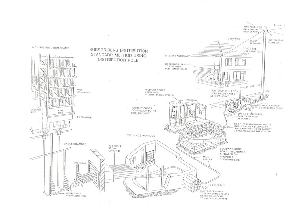
GPO Local Telephone Distribution System
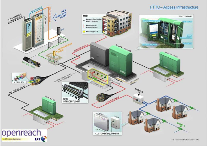
Openreach Local Distribution System
|
|
|
Home Sales Page Nostalgia Fund News Obituaries Local Groups Insurance Issues Dev page for Mobile Friendly
Medical Issues Sport and Leisure Personal Finance BT Company Page Contact Page
|